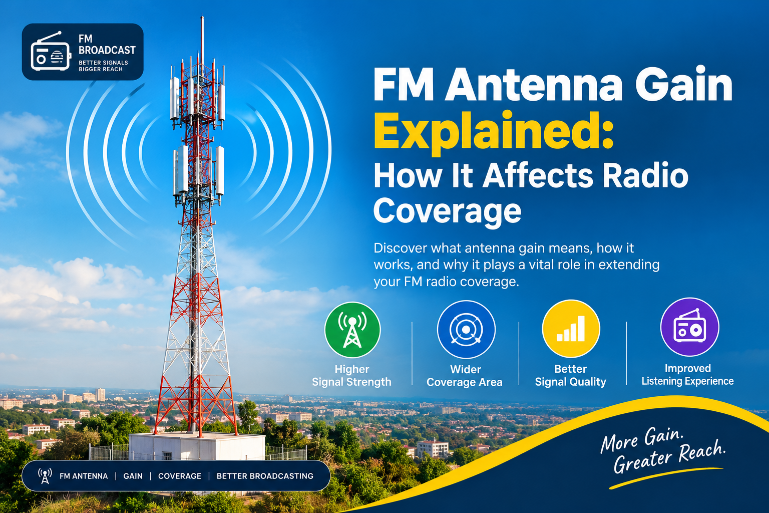
FM Antenna Gain Explained: How It Affects Radio Coverage
If you have ever wondered why two FM radio stations using similar transmitter power can have noticeably different coverage areas, the answer may be found in the antenna system.
A radio station’s coverage is not determined by transmitter power alone. Antenna gain, antenna height, radiation pattern, terrain, frequency, polarization and the design of the antenna array all influence how RF energy is distributed.
One of the most important concepts in broadcast engineering is therefore FM antenna gain.
But what exactly does antenna gain mean, and how does it affect the coverage of an FM radio station?
What Is FM Antenna Gain?
FM antenna gain describes the ability of an antenna system to concentrate electromagnetic energy in particular directions compared with a reference antenna.
It is important to understand that an antenna does not create additional electrical power.
For example, if an FM transmitter produces 10 kW, installing a multi-bay antenna does not turn that transmitter into a 40 kW transmitter. Instead, the antenna system distributes and concentrates the existing RF energy more effectively.
This distinction between transmitter power and antenna gain is fundamental to understanding FM broadcasting.
A simplified relationship is:
ERP ≈ Transmitter Power × Antenna Gain × System Efficiencies
Actual calculations must also consider transmission-line losses, divider or combiner losses, antenna efficiency, gain reference and the radiation pattern.
How Does Antenna Gain Improve FM Coverage?
Antenna gain can improve coverage by concentrating RF energy in useful directions.
Imagine two stations that each have a 10 kW transmitter. If one station uses a relatively simple antenna system while the other uses a carefully engineered multi-bay antenna with greater gain, the second station can potentially produce a stronger signal in its intended coverage area.
The transmitter power may be identical, but the way that power is distributed through space can be very different.
This is why antenna gain and transmitter power should never be treated as the same thing.
FM Antenna Gain vs Transmitter Power
This is one of the most common areas of confusion.
A transmitter determines how much RF power is available to the antenna system. The antenna determines, among other things, how that RF energy is distributed.
Consider a simplified example:
Station A
- Transmitter: 10 kW
- Simple antenna system
- Lower antenna gain
Station B
- Transmitter: 10 kW
- Multi-bay antenna system
- Higher antenna gain
Station B can potentially produce greater ERP in the direction where the antenna gain is applied, even though both transmitters produce the same output power.
This is why a well-engineered antenna system can make a significant difference to FM coverage.
What Are Antenna Bays?
When looking at an FM broadcast tower, you may see several radiating elements mounted vertically near the top.
These elements are often referred to as bays.
A bay is essentially one radiating unit within the larger antenna system. A four-bay antenna, for example, can consist of four coordinated radiating elements fed from a single transmitter rather than four independent radio stations.
FM antenna systems can therefore contain:
- One bay
- Two bays
- Four bays
- Six bays
- Eight bays or more
The number of bays alone, however, does not determine the final performance.
The spacing, phase, amplitude, antenna design, polarization and installation all matter.
How Multiple FM Antenna Elements Create Gain
Consider a transmitter feeding several antenna bays.
The RF signal travels through a transmission line to a power divider or phasing system, which distributes the RF energy to the individual antenna elements.

With a four-bay system, a simplified equal power division could send approximately 2.5 kW toward each bay from a 10 kW transmitter, before accounting for system losses.
However, the important point is not simply how much power reaches each individual bay.
The electromagnetic waves produced by the elements interact with one another.
When the elements are correctly spaced and phased, their radiation can reinforce itself in desired directions. This produces a combined radiation pattern with greater directivity and potentially higher antenna gain.
Why Phasing Matters
Phasing is one of the most important parts of a multi-bay FM antenna system.
When RF signals from different antenna elements reach a particular direction in phase, they can reinforce each other. In other directions, the waves can partially cancel.
This phenomenon is known as:
- Constructive interference — waves reinforce one another.
- Destructive interference — waves partially cancel one another.
Engineers use this principle to shape the antenna’s radiation pattern.
The phasing network therefore plays an important role in determining how the RF energy is distributed.
Why More Antenna Bays Can Increase Gain
Adding more bays can provide greater control over the vertical radiation pattern.
A single bay provides relatively limited pattern control. Two bays provide more control, while four, six or eight bays can provide increasingly sophisticated vertical pattern shaping.
The uploaded engineering material describes the progression conceptually as:
1 bay → basic radiation
2 bays → improved control
4 bays → greater vertical directivity
8 bays → potentially greater vertical directivity and gain
However, these are not universal performance figures. Actual antenna gain depends on the antenna type, spacing, phasing, polarization, feed network and installation.
Antenna Gain and Vertical Radiation Pattern
One of the major advantages of a multi-bay FM antenna is its ability to shape the vertical radiation pattern.
Instead of allowing significant RF energy to be directed at unnecessarily high elevation angles, engineers can design the array to concentrate more energy toward the horizon.
This can make the system more effective for terrestrial FM broadcasting.
The objective is not simply to make the signal “stronger everywhere.” Rather, it is to distribute the available RF energy where it is most useful.
This is known as vertical pattern shaping.
Does More Antenna Gain Always Mean More Coverage?
Not necessarily.
FM coverage depends on several interacting factors, including:
- Transmitter power
- Antenna gain
- Antenna height
- Terrain
- Frequency
- Propagation conditions
- Radiation pattern
- Polarization
- System losses
The source material summarizes this concept as:
Coverage ≈ Power + Antenna Gain + Antenna Height + Terrain + Frequency + Propagation
These factors do not simply add together in real engineering calculations, but they demonstrate why transmitter wattage alone cannot be used to predict coverage.
Antenna Height Is Just as Important
A high-gain antenna installed at a relatively low location may not necessarily outperform a properly designed antenna installed at a much greater height.
For FM broadcasting, antenna height has a major influence on the radio horizon.
The relevant engineering parameter can include Height Above Average Terrain (HAAT) rather than simply the physical height of the tower.
A 300-metre tower does not automatically have the same effective coverage characteristics as another 300-metre tower because the surrounding terrain can be very different.
Therefore, antenna gain and antenna height should be considered together when evaluating FM coverage.
What Does 6 dBd Antenna Gain Mean?
Antenna gain is commonly expressed using units such as dBd.
For example, the source material uses a 6 dBd antenna as a conceptual example. A gain of 6 dBd represents approximately four times the power concentration compared with a half-wave dipole reference, subject to the assumptions and reference used.

The important lesson is that dBd is a measure of antenna performance relative to a reference—not an indication that the transmitter itself has become more powerful.
Omnidirectional vs Directional FM Antennas
Antenna gain can also be associated with the desired horizontal radiation pattern.
An omnidirectional FM antenna is designed to distribute radiation approximately around the station, which can be useful for broad regional coverage.
A directional antenna, on the other hand, deliberately concentrates radiation toward selected areas and may reduce radiation in other directions.
Directional patterns can be used to:
- Protect another station
- Reduce interference
- Comply with licensing requirements
- Focus coverage toward a population centre
- Reduce radiation toward a particular geographic area
Therefore, the highest possible gain is not always the objective. The right radiation pattern is often more important.
Why an 8-Bay Antenna Is Not Automatically Better Than a 4-Bay Antenna
It is tempting to assume that an eight-bay antenna must always outperform a four-bay antenna.
That is not necessarily true.
An eight-bay system can offer greater vertical directivity and potentially higher gain, but it also introduces additional engineering considerations, including:
- Higher tower loading
- Greater wind resistance
- More complex feed networks
- Higher installation costs
- More difficult maintenance
- More complicated impedance matching
- Greater structural requirements
There are also diminishing returns.
The correct antenna configuration depends on the station’s frequency, required coverage, transmitter power, antenna height, terrain, desired ERP, radiation pattern, polarization, regulatory requirements and tower loading.
FM Antenna Gain, ERP and Coverage: The Big Picture
The complete FM transmission chain can be simplified as:
Studio → Audio Processing → FM Exciter → Power Amplifier → Transmitter → Transmission Line → Power Divider/Phasing System → Antenna Bays → Antenna Array → RF Propagation
The transmitter supplies RF power, the transmission system carries it to the tower, the divider and phasing system distribute it among the antenna bays, and the antenna array converts the electrical energy into electromagnetic radiation.
This is why FM coverage is an engineering system rather than simply a question of transmitter wattage.
Final Thoughts
FM antenna gain is one of the key factors influencing radio coverage, but it should never be considered in isolation.
A station’s real-world performance depends on the interaction between transmitter power, antenna gain, antenna height, bay configuration, spacing, phase, amplitude, polarization, radiation pattern, terrain and system efficiency.
Most importantly, more antenna elements do not automatically mean a more powerful transmitter. Multiple bays allow engineers to control and concentrate the distribution of existing RF energy.
Understanding this distinction helps explain why two FM stations with similar transmitter power can have very different coverage areas.
In broadcast engineering, the goal is not simply more power. The goal is efficiently putting the available RF energy where it is needed.
That is the real value of FM antenna gain.